| Looking
Closer:
Let's take a closer look at a couple of
the "features" of this setup. Taking a look at the image
below...

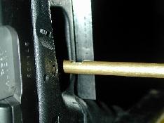
I set the exact midpoint of the trigger
as the location for the harness bar. Note the "blocking" used
to insure the bar stays centered.

I chose to use a bar at the top rather
than the bottom for a couple of very important reasons. As you can see
above, it is very easy to see even the slightest imbalance. If the
weapon is exactly vertical and the bar is perpendicular to the weapon,
then the applied load (force) is acting directly back on the trigger
minimizing side loads. In addition, the bar allows for
future load vs. displacement measurements. This will be necessary to
address inter-pull "hitches" (or large increases in force per
unit of displacement) such as when the trigger bar engages the firing
pin safety plunger et al.
|
|
It's a little easier to see in the image
above. Note the "sight notch" in the bar. It was cut so that a
consistent relationship to the machinist's ruler can be maintained for
determining displacement. By sighting over the notch against the ruler,
I can measure displacement fairly accurately to approximately 1/64"
(0.01563"). The loads can be plotted against displacement in a
graph that will clearly show various "problem" areas in the
pull-through.

Above is an image of the weapon right at
the break point. In fact, the very next case I added to the system
caused the trigger break. It is very important to add weight to the
bag very carefully. Dropping cases into the bag cause momentary "load spikes"
due to the acceleration imparted by the moving case. A load spike near
the break point will cause a premature trigger break at an erroneously
low weight. The cases must be placed
in the bag to minimize acceleration-induced errors. I use a set of
long tweezers.
Next...
|


