|
| |
|
Alternator Upgrade
"More Power!"
|
| Face
it... The OE alternator simply doesn't have the juice necessary to
do what most of us want... Whether your aim is a monster stereo
system, upgraded headlights, bigger electric fans, electric water pump,
etc... A 130 ampere, 3G (third generation) alternator is the
solution. I bought mine from PA-Performance.
They're good folks with whom to deal. Rick Harmon, the owner, spent a lot
of time patiently answering ALL my questions! They also offer housing
coating options, fuse and wiring kits, and even a massive 200 amp, 3G
version now. This article details the installation procedure I used
to install the 130 amp version in my 1989 Mustang Coupe (2.3L) in
preparation for all the electric goodies I plan to add. Now, my
install is into a car that has already been modified for manual rack and
pinion steering, so no OE Power Steering bracket mods were
necessary. But the wiring drill should be applicable to virtually
all Mustangs and can easily be adapted to most other TurboFords.
Disconnect your Batt(+) cable from the
battery and place it such that it cannot accidentally make contact with
the positive lug on the battery. Also... all the images are linked
to larger versions for a little more detail.
|
 Yeah,
my engine bay is still pretty nasty... It'll be cleaned, smoothed, and
painted before the new engine goes in... But, as you can see in the image,
it's simply a typical 2.3L engine bay. The original alternator is
still in place, though the housing was modified to work with the OE upper
alternator bracket and the manual steering Ranger lower alternator
bracket. Yeah,
my engine bay is still pretty nasty... It'll be cleaned, smoothed, and
painted before the new engine goes in... But, as you can see in the image,
it's simply a typical 2.3L engine bay. The original alternator is
still in place, though the housing was modified to work with the OE upper
alternator bracket and the manual steering Ranger lower alternator
bracket.
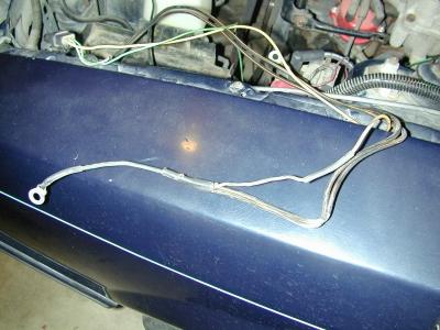
You can see the OE alternator harness
passing over the top of the alternator and down into the "black
hole" beneath the coil and starter relay. Note: some of the harness
has already been broken out during previous harness pairing operations.
|
 Here's
another shot from the top. Note the regulator connector on the
alternator (center/rear). The 3-pin power connector is at the end of the
split loom harness over the top of the alternator. The starter relay (red)
is at the bottom of the image. The relay output is on the left side of the
relay (hidden by the small black boot). It only has the starter power wire
connected to it. On the right side of the relay, you can see the BAT+
terminal loaded down with ring terminals. This side of the relay acts as
the main power distribution lug from the battery to the car AND the power
input lug from the alternator to the battery. Here's
another shot from the top. Note the regulator connector on the
alternator (center/rear). The 3-pin power connector is at the end of the
split loom harness over the top of the alternator. The starter relay (red)
is at the bottom of the image. The relay output is on the left side of the
relay (hidden by the small black boot). It only has the starter power wire
connected to it. On the right side of the relay, you can see the BAT+
terminal loaded down with ring terminals. This side of the relay acts as
the main power distribution lug from the battery to the car AND the power
input lug from the alternator to the battery.
Down below that worn out (+) battery cable
is the bundle of wires we'll be hacking into soon. Also, if you look
closely, you can see the negative battery cable exiting from the rear of
the battery and traveling down and across to the main engine ground (lower
left bolt on the standard Power Steering Housing/Alternator Bracket.
The first thing you need to do is remove
the regulator and power plugs from the OE alternator, and un-bundle the
alternator harness all the way back to the starter relay. Gotta get a look
at those wires... |
 The
harness is un-bundled and draped over the driver's side fender. The
regulator plug is on the left, and the power plug is on the right.
On the regulator plug, you will have three wires. The A-terminal
(Y/W) connects battery power from the BAT+ terminal on the starter relay
via a series of two fuse links to the alternator regulator (always hot:
12vdc). The S-terminal (W/BK) which is the stator wire connected from the
regulator to the stator via the power plug (on this alternator). On
some alternators, it might already be a separate plug, and I've heard of
it not being connected at all... simply left unconnected in the harness.
The I-terminal (LG/R) connects the regulator to Batt(+) via the voltmeter
and the ignition switch (Hot in START or RUN). BTW... if you remove your
instrument cluster, your alternator will not charge the battery unless you
jumper the voltmeter pins. The
harness is un-bundled and draped over the driver's side fender. The
regulator plug is on the left, and the power plug is on the right.
On the regulator plug, you will have three wires. The A-terminal
(Y/W) connects battery power from the BAT+ terminal on the starter relay
via a series of two fuse links to the alternator regulator (always hot:
12vdc). The S-terminal (W/BK) which is the stator wire connected from the
regulator to the stator via the power plug (on this alternator). On
some alternators, it might already be a separate plug, and I've heard of
it not being connected at all... simply left unconnected in the harness.
The I-terminal (LG/R) connects the regulator to Batt(+) via the voltmeter
and the ignition switch (Hot in START or RUN). BTW... if you remove your
instrument cluster, your alternator will not charge the battery unless you
jumper the voltmeter pins. |
 Here
is an image showing the other end of the harness where the BAT(+) power
wires from the alternator and the A-terminal wire join for connection via
the ring terminal to the BAT(+) terminal on the starter relay. Note: The
slender wire between the splice at the ring terminal and the 3-to1 splice
in the center of the picture is a 14GA fusible link wire that is SUPPOSED
to protect the two large power wires coming from the alternator (2x BK/O).
The slender wire section between the 3-to-1 splice and the splice in the
yellow w/ white stripe wire (A-wire) is the 18GA fusible link wire that is
supposed to protect the Y/W wire. We are going to keep the 18GA fusible
link, but delete the 14GA fusible link... Time to snip some wires... Here
is an image showing the other end of the harness where the BAT(+) power
wires from the alternator and the A-terminal wire join for connection via
the ring terminal to the BAT(+) terminal on the starter relay. Note: The
slender wire between the splice at the ring terminal and the 3-to1 splice
in the center of the picture is a 14GA fusible link wire that is SUPPOSED
to protect the two large power wires coming from the alternator (2x BK/O).
The slender wire section between the 3-to-1 splice and the splice in the
yellow w/ white stripe wire (A-wire) is the 18GA fusible link wire that is
supposed to protect the Y/W wire. We are going to keep the 18GA fusible
link, but delete the 14GA fusible link... Time to snip some wires... |
 Clip
the LG/R (I-terminal wire) and Y/W (A-terminal wire) about 1" from
the back side of the regulator connector. then clip the Y/W wire's fusible
link as close to the 3-to-1 splice as possible. You will be left with 1)
LG/R wire open at one end, and disappearing into the harness leading to
the firewall at the other, 2) a length of Y/W wire with an 18GA fusible
link wire at one end, and 3) a bunch of trash wire between the two OE
alternator connectors (this assumes that you are replacing the regulator
connector with a new one from PA-Performance and that you are replacing,
rather than supplementing the OE power wires as I did... and recommend). Clip
the LG/R (I-terminal wire) and Y/W (A-terminal wire) about 1" from
the back side of the regulator connector. then clip the Y/W wire's fusible
link as close to the 3-to-1 splice as possible. You will be left with 1)
LG/R wire open at one end, and disappearing into the harness leading to
the firewall at the other, 2) a length of Y/W wire with an 18GA fusible
link wire at one end, and 3) a bunch of trash wire between the two OE
alternator connectors (this assumes that you are replacing the regulator
connector with a new one from PA-Performance and that you are replacing,
rather than supplementing the OE power wires as I did... and recommend). |
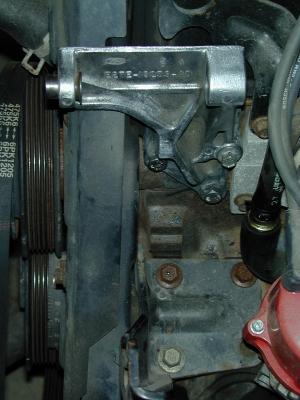
 With
the old wiring out of the way, switch gears a minute and get the bracket(s)
prepared to install the new 3G alternator. If, for some bizarre reason,
you still have power steering, you MAY need to use a die grinder or other
suitable tool to grind away a bit of material from the PS housing to
clearance for the new alternator. I however have manual steering,
and am temporarily using the upper and lower brackets from a manual
steering '91 Ranger. The image at right shows a comparison between
the stock upper bracket, and the Ranger upper bracket (bottom). The Ranger
flips the alternator. Of particular note is the thinner bolt bosses
on 2 of the 3 bolt holes... With
the old wiring out of the way, switch gears a minute and get the bracket(s)
prepared to install the new 3G alternator. If, for some bizarre reason,
you still have power steering, you MAY need to use a die grinder or other
suitable tool to grind away a bit of material from the PS housing to
clearance for the new alternator. I however have manual steering,
and am temporarily using the upper and lower brackets from a manual
steering '91 Ranger. The image at right shows a comparison between
the stock upper bracket, and the Ranger upper bracket (bottom). The Ranger
flips the alternator. Of particular note is the thinner bolt bosses
on 2 of the 3 bolt holes... |
 You
can re-use one of the OE bolts from the PS housing, but you'll need 2
shorter bolts to properly mount the Ranger upper bracket. Either get them
with the bracket from the donor, or use new hardware (M8). The shorter
bolts I used are 25mm in length. They will work fine, but you can go as
long as 30-32mm if you choose. You
can re-use one of the OE bolts from the PS housing, but you'll need 2
shorter bolts to properly mount the Ranger upper bracket. Either get them
with the bracket from the donor, or use new hardware (M8). The shorter
bolts I used are 25mm in length. They will work fine, but you can go as
long as 30-32mm if you choose. |
 From
the top, you can see that both brackets are installed. Be sure to
use thread locker on all the bracket bolts; you definitely do not want any
of them getting loose. The Ranger setup moves the long pivot bolt to the
top and uses a steel, swing-arm for the bottom. It also uses a horizontal
brace from the lower bracket to the lower intake, but this isn't really
necessary on our cars, and in my case, the brace was too short to reach
the blank bolt boss on my lower intake. I simply removed it. Be sure to
press the pivot bolt bushing into the upper bracket some to make inserting
the alternator into the upper bracket easier. From
the top, you can see that both brackets are installed. Be sure to
use thread locker on all the bracket bolts; you definitely do not want any
of them getting loose. The Ranger setup moves the long pivot bolt to the
top and uses a steel, swing-arm for the bottom. It also uses a horizontal
brace from the lower bracket to the lower intake, but this isn't really
necessary on our cars, and in my case, the brace was too short to reach
the blank bolt boss on my lower intake. I simply removed it. Be sure to
press the pivot bolt bushing into the upper bracket some to make inserting
the alternator into the upper bracket easier.
You can install the alternator now if you
choose. As I said, the Ranger brackets clock the alternator 180
degrees, so a stock alternator would have the plugs on the bottom as
installed. The 3G has its plugs on the opposite side of the housing,
so my harness routing will remain the same... to the top side. A 3G
on an OE power steering housing will move the harness routing under the
alternator. |
 Back
to the wiring stuff... I use solder connections (or solder AND
crimp). I never use crimp only connections. Solder the
included 1-wire stator plug to the W/BK wire (S-terminal) on the new
regulator plug. Then solder the Y/W (A-terminal) wire to the Y/W on the
regulator plug. Solder a short piece of wire the same gauge as the
Y/W wire to the fusible link wire on the other end. Then terminate this
short piece of wire with an appropriately sized ring terminal (to fit over
the starter relay BAT(+) terminal). Then solder the loose LG/R wire from
the car harness to the LG/R wire on the regulator plug (I-terminal).
That's it for the regulator plug and stator plug... Back
to the wiring stuff... I use solder connections (or solder AND
crimp). I never use crimp only connections. Solder the
included 1-wire stator plug to the W/BK wire (S-terminal) on the new
regulator plug. Then solder the Y/W (A-terminal) wire to the Y/W on the
regulator plug. Solder a short piece of wire the same gauge as the
Y/W wire to the fusible link wire on the other end. Then terminate this
short piece of wire with an appropriately sized ring terminal (to fit over
the starter relay BAT(+) terminal). Then solder the loose LG/R wire from
the car harness to the LG/R wire on the regulator plug (I-terminal).
That's it for the regulator plug and stator plug... |
 Of
course, you need to put a length of shrink tubing on the wire before
soldering, then shrink it over the connection. PLEASE don't use electrical
tape!! Shrink tubing is cheap, won't come loose, and won't get
sticky and nasty... Personally, I very often use two layers of
shrink tubing over my solder splices in auto harnesses just to make sure. Of
course, you need to put a length of shrink tubing on the wire before
soldering, then shrink it over the connection. PLEASE don't use electrical
tape!! Shrink tubing is cheap, won't come loose, and won't get
sticky and nasty... Personally, I very often use two layers of
shrink tubing over my solder splices in auto harnesses just to make sure. |
 Now,
you still have to connect the power lug on the alternator to the BAT(+)
terminal on the starter relay, AND you have to add circuit
protection. PA-Performance's instructions are based on supplementing
the two OE power wires with a third power wire into which a Little Fuse
Mega 200amp fuse is inserted... I say, why use three wires, when you can
do it with one wire AND eliminate two "electric matches" (my
term for fusible links in high current circuits). Now,
you still have to connect the power lug on the alternator to the BAT(+)
terminal on the starter relay, AND you have to add circuit
protection. PA-Performance's instructions are based on supplementing
the two OE power wires with a third power wire into which a Little Fuse
Mega 200amp fuse is inserted... I say, why use three wires, when you can
do it with one wire AND eliminate two "electric matches" (my
term for fusible links in high current circuits).
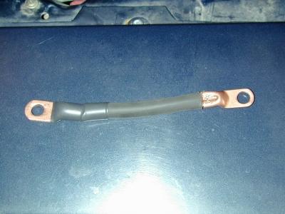
I used #4 welding cable and solid copper
solder/crimp lugs. Yeah, it's probably overkill, but there is zero chance
that the cable will blow before the fuse, and the large cable minimizes
voltage drop between the alternator and the battery... less voltage drop
means more efficient/quicker charging. Welding cable has many more strands
than standard battery cable and is much more flexible. Pictured is the
alternator to fuse block cable. |
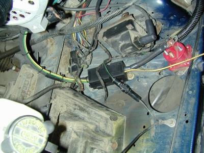
 Here
you can see that I've installed the alternator to fuse block power cable.
I've also zip tied all the regulator wiring to the power cable for neat
routing across and up to the starter relay. I've left it open to
illustrate the routing. This harness MUST be wrapped, preferably with
self-fusing silicone tape to protect the neoprene insulation on the
welding cable, as neoprene and petroleum products don't play well
together. Note that the W/BK stator wire is simply folded and
bundled neatly along the cable. The"A" and "I"
terminal wires are zip tied neatly across to the apron with the power
cable. None of the BAT(+) connections have been made yet, as I also
replaced my battery cables while I was at it. Here
you can see that I've installed the alternator to fuse block power cable.
I've also zip tied all the regulator wiring to the power cable for neat
routing across and up to the starter relay. I've left it open to
illustrate the routing. This harness MUST be wrapped, preferably with
self-fusing silicone tape to protect the neoprene insulation on the
welding cable, as neoprene and petroleum products don't play well
together. Note that the W/BK stator wire is simply folded and
bundled neatly along the cable. The"A" and "I"
terminal wires are zip tied neatly across to the apron with the power
cable. None of the BAT(+) connections have been made yet, as I also
replaced my battery cables while I was at it. |
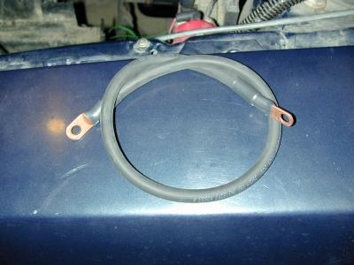
 Here
is the shorter, fuse block to starter relay power cable of the same #4
welding cable. Note the two different size lugs. The bigger size
fits the fuse block snugly, and the smaller size is required for the
alternator and starter relay connections (both cables). You can see how
the lugs are crimped onto the cable. I used a large screwdriver and my
bench vise. A proper crimp tool is preferable if available. BE SURE to
double shrink tube the ends of the cables to minimize the exposed copper
to guard against accidental shorts to ground. Also, if you use adhesive
lined shrink tube, you can prevent moisture infiltration into the copper
cable and the accompanying corrosion. Here
is the shorter, fuse block to starter relay power cable of the same #4
welding cable. Note the two different size lugs. The bigger size
fits the fuse block snugly, and the smaller size is required for the
alternator and starter relay connections (both cables). You can see how
the lugs are crimped onto the cable. I used a large screwdriver and my
bench vise. A proper crimp tool is preferable if available. BE SURE to
double shrink tube the ends of the cables to minimize the exposed copper
to guard against accidental shorts to ground. Also, if you use adhesive
lined shrink tube, you can prevent moisture infiltration into the copper
cable and the accompanying corrosion. |
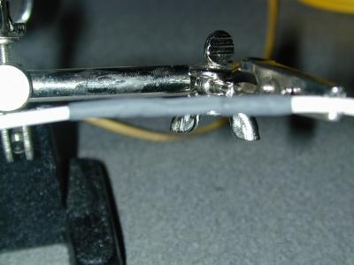
 Here
is a close-up of the MEGA fuse holder with the two cables attached and
bridged with the 200 amp fuse. I chose to route the extra LG/R wire up
along the power cable to make it neater. I also ran the Y/W
(A-terminal) wire along the same route since it and the power cable
terminate at the same place... neater. Here
is a close-up of the MEGA fuse holder with the two cables attached and
bridged with the 200 amp fuse. I chose to route the extra LG/R wire up
along the power cable to make it neater. I also ran the Y/W
(A-terminal) wire along the same route since it and the power cable
terminate at the same place... neater.
In this picture you can see that I simply
mounted the fuse block to the apron using some sheet metal hardware I had
handy. I used a die grinder to cut the flat in the captured washer, and
used a single edge razor blade to trim the fuse holder tab for a flush fit
to the washer. Note also that I made sure not to let the shrink tubing far
enough down on the lug so as to interfere with the flush mounting of the
lug to the fuse tab. |
 This
image shows the fuse holder cover installed. Wrap the alternator harness
with black self-fusing silicone tape, and it'll basically disappear.
All that is left to do now is route and reconnect all the terminals to the
starter relay... oh, and of course in my case, I have to re-install the
battery and make the new battery cables. This
image shows the fuse holder cover installed. Wrap the alternator harness
with black self-fusing silicone tape, and it'll basically disappear.
All that is left to do now is route and reconnect all the terminals to the
starter relay... oh, and of course in my case, I have to re-install the
battery and make the new battery cables. |
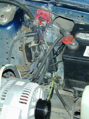 Here
is the completed install (sans the new alternator belt). It may take some
creativity to get all the terminals on the starter relay, but it's doable.
I am eliminating the starter relay when I install the mini-starter, and
replacing it with either a larger distribution terminal or a bus bar
arrangement to make things a bit cleaner/easier. Most likely I will move
the BAT(+) distribution point to the firewall (probably INSIDE the
firewall) since the battery is going to be moved to either the trunk or
passenger rear foot well. Moving the distribution point to the firewall
will make the battery cable runs shorter and allow for the elimination of
about 2.5' of wire from each of the main distribution circuits as they
travel from the starter relay to the ignition switch and/or the interior
fuse block. Additionally, I will be eliminating all the fusible
links and the entire interior fuse block in favor of aviation style
push/pull circuit breakers of the appropriate type and rating. Here
is the completed install (sans the new alternator belt). It may take some
creativity to get all the terminals on the starter relay, but it's doable.
I am eliminating the starter relay when I install the mini-starter, and
replacing it with either a larger distribution terminal or a bus bar
arrangement to make things a bit cleaner/easier. Most likely I will move
the BAT(+) distribution point to the firewall (probably INSIDE the
firewall) since the battery is going to be moved to either the trunk or
passenger rear foot well. Moving the distribution point to the firewall
will make the battery cable runs shorter and allow for the elimination of
about 2.5' of wire from each of the main distribution circuits as they
travel from the starter relay to the ignition switch and/or the interior
fuse block. Additionally, I will be eliminating all the fusible
links and the entire interior fuse block in favor of aviation style
push/pull circuit breakers of the appropriate type and rating.
In this image, you can see that the new
battery cables have been installed. Since the runs are so short, I only
used #2 welding wire. Quite a bit larger than the standard battery cables,
they still keep voltage drop to a minimum, but are flexible enough for
easy routing and useable with my old quick release battery connectors. |
 From
the top, mod complete... except for the belt and tightening the alternator
bolts... From
the top, mod complete... except for the belt and tightening the alternator
bolts...
I put the alternator at it's adjustment
extremes and used a tailor's tape to measure the circumference around the
crankshaft power pulley, water pump pulley, and alternator pulley. For
those who are curious, the minimum is 44" and the maximum is
46.75". I chose a Kelly 445K6 belt (44.5" 6-rib
serpentine). This gets the alternator down about as low as it will go...
maybe even low enough to pass a rotated upper intake over the top....
probably not quite though. |
| Well,
that's it... That'll get me by until I get the engine swap complete,
finish the bracket to mount the alternator low on the passenger's side,
install the 1-V Esslinger pulleys (new engine), and/or install the
electric water pump. I will likely do the water pump before the engine
swap, so I can complete the testing of the flow controller and water pump
eliminator inlet plate I have designed.
Oh yeah... it works great! With
the OE alternator, you could see the headlights dim at night when you hit
the brakes or opened/closed one or both of the electric windows...
With the new alternator, the headlights have never been brighter, and
there is no flicker no matter what is on or what you turn on/off.
|
| |
|


