|
Anal Retentive's Guide to
File-to-Fit Piston Rings
|
|
Part of the build-up for my
new engine necessitates filing the Total
Seal TS1 Rings to fit the cylinder bores properly. It
occurred to me that some folks may not have ever done this, and that it
might be a good idea to put together a "How-To" guide on ring
filing. Now, as anyone who knows me will tell you, I am
somewhat particular about how I do certain things.... well everything
actually. So, this article illustrates the method "I" used
to fit my piston rings.
Note: Click on any image
to pop up a larger version. If your browser "auto-resizes"
it, you can hover your mouse cursor over the picture to bring up the
"size-toggle" button in the lower right-hand corner of the
image. Click on that button to see the image full size.
|
 Here
are the basic tools and materials I used: manual crank ring filer
clamped to table with a 12' clamp, 320 grit wet-dry paper on a sanding
block, flat diamond file, feeler gauge set, ring squaring tool, and of
course the Total Seal documentation for the TS1 Gapless Second Ring set. Here
are the basic tools and materials I used: manual crank ring filer
clamped to table with a 12' clamp, 320 grit wet-dry paper on a sanding
block, flat diamond file, feeler gauge set, ring squaring tool, and of
course the Total Seal documentation for the TS1 Gapless Second Ring set.
I bought both the ring filer and the
squaring tool from a Total Seal dealer here locally. If you don't
have these tools, get them. They are not optional. You can't
do a proper file-to-fit job without them. |
 Beginning
with the top compression ring, refer to the documentation and you'll find
where it says to install the ring with the bevel located on the inner
diameter FACE UP. Thus you should file the rings the same way, with
the bevel UP. Beginning
with the top compression ring, refer to the documentation and you'll find
where it says to install the ring with the bevel located on the inner
diameter FACE UP. Thus you should file the rings the same way, with
the bevel UP. |
 Next
thing I do is to install the raw ring in the bore to get a quick
pre-measurement to see where I am at. You should install the ring
oriented to the cylinder just how it will be installed on the
piston. In this case, the ring is 180 degrees reversed from where it
should be, but I'm just getting a quick reference for starting
purposes. Next
thing I do is to install the raw ring in the bore to get a quick
pre-measurement to see where I am at. You should install the ring
oriented to the cylinder just how it will be installed on the
piston. In this case, the ring is 180 degrees reversed from where it
should be, but I'm just getting a quick reference for starting
purposes.
Note: it should go without saying, but you
MUST install the ring in the cylinder bore into which you will install the
ring during final installation. The way I do it is to take all the
rings out of the box and make up individual cylinder "ring
sets". Then I place each ring set in its own Ziplock bag, and
label it with the corresponding cylinder number. AND I NEVER have
more than ONE bag open at a time.
|
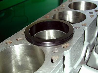 Use
the ring squaring tool to square the ring in the cylinder bore. This
tool pushes the ring down in the hole about 1". Note:
When you order the tool, be sure to get the largest diameter one that will
still fit inside the bore. In this case, the tool is designed for
piston bores with a size range of 3.810"-3.900" and is Total
Seal Part# 8900. Use
the ring squaring tool to square the ring in the cylinder bore. This
tool pushes the ring down in the hole about 1". Note:
When you order the tool, be sure to get the largest diameter one that will
still fit inside the bore. In this case, the tool is designed for
piston bores with a size range of 3.810"-3.900" and is Total
Seal Part# 8900. |
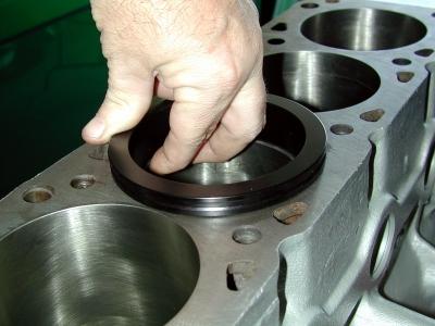 Holding
the tool flat against the block deck, use your fingers to double check
that the ring is flush against the face of the squaring tool all the way
around. Holding
the tool flat against the block deck, use your fingers to double check
that the ring is flush against the face of the squaring tool all the way
around. |
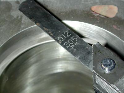
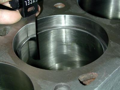 Use
the feeler tool, measure your starting place. Note in the image, that the
blade is NOT flush against the wall of the cylinder bore. This is a
BAD measurement. The blade enters the gap, but won't fully
seat. This indicates gap faces that are not square. Use
the feeler tool, measure your starting place. Note in the image, that the
blade is NOT flush against the wall of the cylinder bore. This is a
BAD measurement. The blade enters the gap, but won't fully
seat. This indicates gap faces that are not square. |
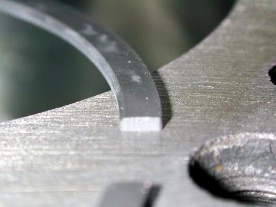
 A
couple of revolutions on the ring filer confirms that the faces are NOT
true. Note in the image the shiny portion of the gap face. A
couple of revolutions on the ring filer confirms that the faces are NOT
true. Note in the image the shiny portion of the gap face.
You should file BOTH faces just until the
face is flat (equally shiny across the entire face). Don't get
carried away and file too much. You don't want to open the gap too
wide.
|
 Place
the ring on the filer with the wheel in the center of the gap, and the
inside ring faces touching the posts on either side of the wheel... Place
the ring on the filer with the wheel in the center of the gap, and the
inside ring faces touching the posts on either side of the wheel... |
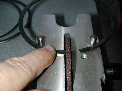 Now,
keeping the ring against the posts, rotate it until the gap face contacts
the abrasive wheel. Hold the ring down tightly with your finger et
al. device. Then begin filing by turning the handle/wheel AWAY from
you. This is so the filing motion is toward the INSIDE of the
ring. This is very important. The abrasive wheel will leave a
sharp bur on the exit side. If this bur is on the bore face, it may
scratch the bore, and it will at minimum hold the ring away from the
cylinder wall. Now,
keeping the ring against the posts, rotate it until the gap face contacts
the abrasive wheel. Hold the ring down tightly with your finger et
al. device. Then begin filing by turning the handle/wheel AWAY from
you. This is so the filing motion is toward the INSIDE of the
ring. This is very important. The abrasive wheel will leave a
sharp bur on the exit side. If this bur is on the bore face, it may
scratch the bore, and it will at minimum hold the ring away from the
cylinder wall.
File a little bit off the gap face...
|
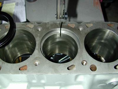
 Insert
the ring into the bore with the squaring tool as described above.
use the feeler gauge to determine the "good" starting gap
measurement. Insert
the ring into the bore with the squaring tool as described above.
use the feeler gauge to determine the "good" starting gap
measurement.
The standard I use for what is a
"GO" and "NO GO" on the feeler gauge is:
A "GO" is when the feeler gauge
will drop vertically through the gap under its own weight.
A "NO GO" is of course when it
will NOT slip down under its own weight.
Here we have a "GO" measurement,
as the feeler gauge dropped into the gap under its own weight and is
resting on the block deck.
Also note that the blade is flush against
the cylinder wall.
|
 Here
is the starting measurement for this ring on this cylinder. I do
this so I will know approximately how much material needs to be removed. Here
is the starting measurement for this ring on this cylinder. I do
this so I will know approximately how much material needs to be removed.
Now, remove the ring CAREFULLY from the
bore, and begin filing it a little at a time. Reinsert into the bore,
square it up and re-measure.
Repeat this procedure until you achieve the
required ring gap for that specific ring for your application. As
you do it more, you'll get a "feel" for how much material to
take off. But it's better to file material off VERY gradually to
make sure you don't overshoot the required gap.
You can ALWAYS take more material off, but
it's impossible to put it back!
Lather, Rinse, Repeat... |
 I've
repeated the file, install, measure procedure about 6 times, and have the
gap exactly where I want it... I've
repeated the file, install, measure procedure about 6 times, and have the
gap exactly where I want it... |
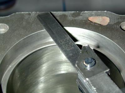 For
this ring and my application, the gap is 0.022". For
this ring and my application, the gap is 0.022".
Total Seal includes a table/formula in its
documentation to assist you in determining an APPROXIMATE ring gap.
However, certain factors in your application may/will require you to
increase or decrease the gap size. in my case, I have widened the
suggested gap by a few thousandths of an inch due to it being a
turbocharged engine AND because the block is filled.
|
 Just
so you can see an example, here is a picture of the feeler gauge set at
0.023" on the ring above. Note that although the feeler gauge
went into the gap fairly easily, it would NOT drop through the gap under
its own weight. Just
so you can see an example, here is a picture of the feeler gauge set at
0.023" on the ring above. Note that although the feeler gauge
went into the gap fairly easily, it would NOT drop through the gap under
its own weight.
Also, note that I have the ring gap
oriented as it will be installed. |
 I
have the right gap size now, but I am not finished with this ring.
Filing the ring causes burs around the edges of the gap face. These
burs will reduce the side and back clearances for the ring to
piston. They will also chew an aluminum piston ring groove to
pieces. You have to take these burs off completely. I
have the right gap size now, but I am not finished with this ring.
Filing the ring causes burs around the edges of the gap face. These
burs will reduce the side and back clearances for the ring to
piston. They will also chew an aluminum piston ring groove to
pieces. You have to take these burs off completely. |
 I
use a combination of this diamond flat file and a sanding block with 320
grit wet/dry sandpaper or finer. File/sand the burs off being
careful not to remove more material than absolutely necessary. I
use a combination of this diamond flat file and a sanding block with 320
grit wet/dry sandpaper or finer. File/sand the burs off being
careful not to remove more material than absolutely necessary. |
 Here
is the machined gapless second compression ring just after I have done the
initial facing procedure. Note the bevel on the inside face, and the
step machined into the outside face to accept the rail. This ring is
currently UPSIDE DOWN. It installs into the bore with the bevel and
step facing down. Here
is the machined gapless second compression ring just after I have done the
initial facing procedure. Note the bevel on the inside face, and the
step machined into the outside face to accept the rail. This ring is
currently UPSIDE DOWN. It installs into the bore with the bevel and
step facing down.
The filing procedure for the gapless second
ring is essentially the same as the top compression ring except that you
have to file the rail too.
I file them separately since the rail tends
to slide back into the groove when done at the same time.
Note: the rail when installed on the
machined ring is slightly undersized in diameter. This is
normal. It expands when in use to seal against the cylinder bore.
Thus it is not necessary to cut the gap in the rail quite as large as the
one used on the machined ring.
The oil ring rails are done the same exact
way as the top ring, though mine were above the minimum required out of
the box. |
| Well,
that's it... That should give you a good start, and a good idea as to the
detail I go into to insure that nothing is overlooked. In my
opinion, you can never be TOO anal retentive when building up a high
horsepower engine.
Have fun, and be safe!
Clay
|


