|
Tubular Front Suspension:
Part 1
Removal of OEM Suspension Parts
|
|
This is Part 1 of a multi-part
series detailing the installation of a tubular front suspension into a
Fox-body Mustang. This installment covers the removal of all
the OEM parts. I have probably "over-illustrated" the
process, but for the sake of the folks new to tearing into a front
suspension, I tried to err on the side of caution.  Speaking of caution: I do not recommend that anyone attempt this
project without the proper skills, tools, and some company. Never
work on an elevated vehicle alone! Additionally, I do not guarantee
that the procedures I have used are safe and/or correct. Follow
these procedures with caution and AT YOUR OWN RISK! I will not be
held liable, should you injure yourself or damage your car. With
that disclaimer covered, I will say that the following procedure was
successful for me.
Speaking of caution: I do not recommend that anyone attempt this
project without the proper skills, tools, and some company. Never
work on an elevated vehicle alone! Additionally, I do not guarantee
that the procedures I have used are safe and/or correct. Follow
these procedures with caution and AT YOUR OWN RISK! I will not be
held liable, should you injure yourself or damage your car. With
that disclaimer covered, I will say that the following procedure was
successful for me.
Note: Click on any image
to pop up a larger version. If your browser "auto-resizes"
it, you can hover your mouse cursor over the picture to bring up the
"size-toggle" button in the lower right-hand corner of the
image. Click on that button to see the image full size.
|
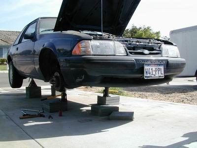 Here's
my 1989 Mustang Coupe. I have placed the rear up on jack stands
which I have further elevated with concrete pavers (4 each side).
The jack stands are located under the axle tubes. Here's
my 1989 Mustang Coupe. I have placed the rear up on jack stands
which I have further elevated with concrete pavers (4 each side).
The jack stands are located under the axle tubes.
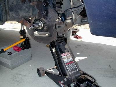
Up front, I used 3 pavers on each side to
elevate the 6-ton bottle jacks. The bottle jacks are located under
the sub-frames just aft of the K-member rear mounting points. I used
bottle jacks in the front to make it easier to level the car from side-to
side in an attempt to load the unibody equally. Use a plumb bob to
measure from the center of the head of the inboard k-member bolt on each
side. Use the bottle jack to raise the low side to equal the high
side.
Ideally, you would use four (4) bottle
jacks, so that you could level each corner to a flat reference
plane. The current work surface is no where near "true",
so I am only leveling from side to side. The critical suspension
setup steps will be done with the car in the garage, using 4 bottle jacks,
corner scales, 4 plumb bobs, et al. aids.
Note that the concrete under the car is
relatively clean. Keep it that way. |
 Break
torque on the lug nuts BEFORE you elevate the car. Remove the wheels
and get them out of the way. If your wheel wells are abnormally
filthy, you should consider cleaning them out before starting work. Break
torque on the lug nuts BEFORE you elevate the car. Remove the wheels
and get them out of the way. If your wheel wells are abnormally
filthy, you should consider cleaning them out before starting work.
Remove the caliper bolts. Slide the
calipers off the rotor and tie them up out of the way in the wheel well.
DO NOT let the calipers hang by the hoses.
Reinstall the caliper bolts into the
spindle.
Remove the wheel bearing dust cover.
I'm sure there is a special tool for the job, but I use an old
screwdriver and a hammer. Caution: Do not drive the
screwdriver too far or you will distort and/or perforate the dust
cover. Work your way around the cover trying to pull it off evenly.
|
 Next,
remove the cotter pin that holds the stamped metal spindle nut cover in
place. NEVER re-use cotter pins. Discard the pin upon removal
and use a NEW pin if you are installing the same/same type rotor/hub. Next,
remove the cotter pin that holds the stamped metal spindle nut cover in
place. NEVER re-use cotter pins. Discard the pin upon removal
and use a NEW pin if you are installing the same/same type rotor/hub.
Remove the spindle/bearing nut cover. |
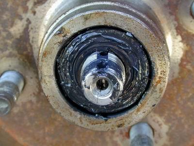
 After
accomplishing the previous step, the image at right should be what you
have in front of you. After
accomplishing the previous step, the image at right should be what you
have in front of you.
Use a metric socket to remove the
spindle/bearing nut. It shouldn't be tight at all, but SHOULD
require a socket/wrench to remove. If you can remove it with your
fingers, then it was NOT properly installed.
By the way, be sure to have several clean
rags right next to you. You'll need them.
|
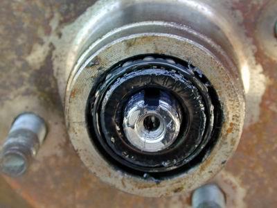
 Nut
removed... Nut
removed...
Now, remove the thrust washer. |
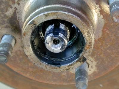
 Washer
removed... Washer
removed...
Now remove the outer wheel bearing.
Use one of those rags I mentioned to wipe
the majority of the bearing grease off of the parts as you remove them.
It's also handy to have a Ziplock bag into
which you can place the small parts to keep contamination away from them,
especially if you plan to reuse the parts. Mark the bags to indicate
the side from which they were taken: Passenger/Driver (Don't use
Left/Right unless you specify "as sitting in driver's seat or some
other reference.)
|
 Front
wheel bearing removed... Front
wheel bearing removed...
Now, remove the rotor from the
spindle. Use care not to drag the rotor across the spindle threads,
and guard against dropping the inner wheel bearing out of the rotor and
onto the ground.
As a general rule, if I drop a bearing on
the ground, it's trash. No way to guarantee that you won't have
sand/grit et al. in the bearing after it touches the ground.
Remove the inner bearing and place it in
the bag with the other small parts. IF you intend to reuse the
parts, be sure to mark one of the bearings to differentiate inner from
outer wheel bearing. |
 Rotor
removed... Rotor
removed...
Now, take one of those rags I spoke of
earlier and clean all the grease off the spindle and out of the recesses
in the dust shield.
|
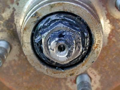
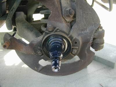
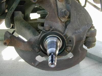 Here's
a nice clean spindle... Here's
a nice clean spindle...
As a guard against contamination/corrosion,
wrap the "shiny" portions of the spindle with a CLEAN rag
partially soaked in some sort of lubricant, like 30w oil. use some
sort of tie/band to secure the rag to the spindle to keep it from falling
off and exposing the spindle to damage/contamination/corrosion.
Note: I did not immediately cover the
spindle because 1) I am not re-using it, and 2) I plan to thoroughly clean
the spindle with solvent, et al. to prepare it for recycling. |
 Next,
we move to the tie-rod ends. You need to remove them from the
spindle to make it easier to remove both the spindle and the rack.
Note: DO NOT rotate the tie-rod end. Leave it exactly as it
was installed to maintain your reference for toe adjustment during
re-installation of the rack. Next,
we move to the tie-rod ends. You need to remove them from the
spindle to make it easier to remove both the spindle and the rack.
Note: DO NOT rotate the tie-rod end. Leave it exactly as it
was installed to maintain your reference for toe adjustment during
re-installation of the rack.
First, remove the cotter pin from the
castellated nut.
|
 Pin
removed... Once again, discard the old pin. Do not re-use cotter
pins... ever. Pin
removed... Once again, discard the old pin. Do not re-use cotter
pins... ever.
Now... there are a couple of ways to do
this next step, But I prefer to use the right tool for the job.
Loosen the castellated nut until it is
flush with the top of the ball joint. |
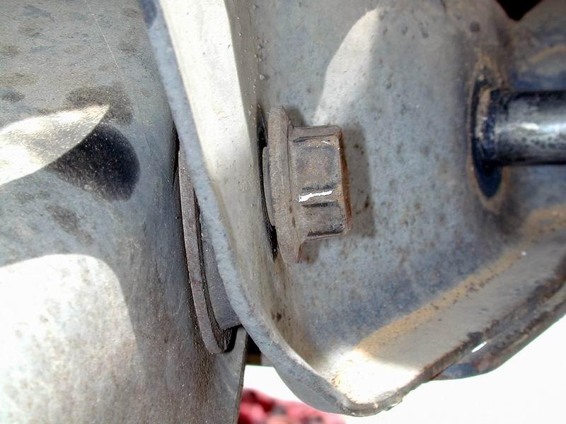
 Note
the nut is flush with the top of the ball joint threads. This does
two things: 1) it keeps the tie-rod from dropping out on separation and
possibly damaging the threads, and 2) it protects the threads should the
tool pop off the indention in the tip of the ball joint. Note
the nut is flush with the top of the ball joint threads. This does
two things: 1) it keeps the tie-rod from dropping out on separation and
possibly damaging the threads, and 2) it protects the threads should the
tool pop off the indention in the tip of the ball joint.
Separate the rod end from the spindle with
a tool like this. I prefer to use a socket to tighten the tool
rather than a wrench... Wrenches (for me) seem to cause the tool to
pop off prematurely.
These tools can be had at almost any auto
parts store for a reasonable price. There are several sizes, so be sure to
get the right one. AutoZone generally has a loaner set that you can sign
out.
Once the tie-rod end is separated from the
spindle, remove the nut completely and pull the tie rod down and
away from the spindle. Replace the nut onto the threads flush with
the top again to protect the threads.
|
 Once
both tie-rod ends are free, disconnect the steering shaft from the
rack. I didn't illustrate this step because I use a Flaming River
steering shaft which uses universal joints rather than the OE rag
joints. No need to breed confusion here. Once
both tie-rod ends are free, disconnect the steering shaft from the
rack. I didn't illustrate this step because I use a Flaming River
steering shaft which uses universal joints rather than the OE rag
joints. No need to breed confusion here.
Remove the two rack bolts, and then remove
the rack from the vehicle.
NOTE: if you still have a power rack,
you'll also, of course, have to disconnect the hydraulic lines. This
is an great time to flush your power steering pump, lines, adn rack.
Better yet, use this opportunity to dump the power steering altogether and
install a manual rack. |
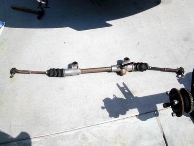 Manual
rack is removed from the car... Looks like I have some clean up and
painting/plating to do on this rack as well as the steering shaft. Manual
rack is removed from the car... Looks like I have some clean up and
painting/plating to do on this rack as well as the steering shaft. |
 Front
side of the k-member with rack removed... Front
side of the k-member with rack removed... |
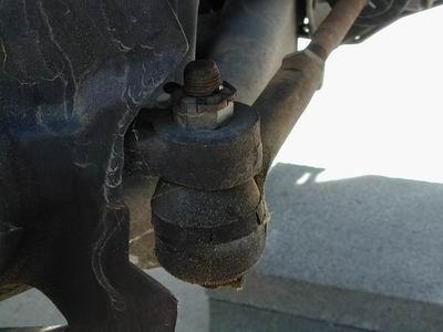
 Next,
you need to remove the sway bar links... Use a socket on the nuts
(top and bottom), and back yourself up with a crescent wrench on the flat
located at the center of each link. Next,
you need to remove the sway bar links... Use a socket on the nuts
(top and bottom), and back yourself up with a crescent wrench on the flat
located at the center of each link.
Be sure to re-assemble the link/bushings,
nuts in the same orientation off the car if you plan to reuse them.
My bushings are trash, but i replaced the nuts to protect the
threads. I may or may not be re-using the link hard parts.
|
 Break
torque and loosen the front bolts in the control arms. These bad boys are
on tight, so use some penetrating spray on them; let them soak; and save
yourself some heartache by using a breaker bar on them. Break
torque and loosen the front bolts in the control arms. These bad boys are
on tight, so use some penetrating spray on them; let them soak; and save
yourself some heartache by using a breaker bar on them.
Do NOT try to remove the bolts!!!
Just loosen them a bit.
besides being a futile effort, if you WERE
to happen to get them out, you'd likely get a broken hand/arm/leg when the
spring popped out on you.
|
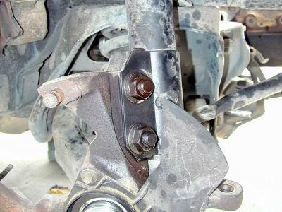
 Break
torque and loosen the rear bolts in the control arms. Break
torque and loosen the rear bolts in the control arms. |
 Break
torque and slightly loosen the strut to spindle bolts. Again, you'll
want to use penetrating spray and a breaker bar. Break
torque and slightly loosen the strut to spindle bolts. Again, you'll
want to use penetrating spray and a breaker bar. |
 Now,
here is where I take a short cut. I do NOT recommend that ANYONE do
this. Now,
here is where I take a short cut. I do NOT recommend that ANYONE do
this.
The PROPER way to do this step is to
install an internal spring compressor on the coil spring to remove the
spring tension from the control arm...
Orient a floor jack as shown in the photo,
and slightly load the jack up against the bottom of the control arm.
Make sure it is securely located.
|
 Now,
keeping your body, legs, and other valuable parts well out of the possible
trajectory of a free flying coil spring, remove the nut from the strut
shaft and place it somewhere where you won't lose it... preferably in its
own little bag, labeled. Now,
keeping your body, legs, and other valuable parts well out of the possible
trajectory of a free flying coil spring, remove the nut from the strut
shaft and place it somewhere where you won't lose it... preferably in its
own little bag, labeled.
Now, go back to the jack, and VERY
carefully ease the hydraulic release open on it. Be prepared to shut
the release quickly should the control arm start to descend too rapidly.
Lower the control arm slowly until the
strut shaft clears the bottom of the camber/caster adjustment assembly
(OEM or aftermarket). Halt the jack to jold it in this
position. Now, cautiously reach up into the wheel well and compress
the strut shaft sufficiently into the strut body so that you can swing the
shaft outboard and clear of the wheel well.
Let the strut hand outboard. Ease the
hydraulic release open on the jack and continue to SLOWLY lower the
control arm. Right about the time the control arm begins to point to
the ground the spring will pop loose and fall out... |
 Coil
spring removed. Put the isolation pad back on the spring top in the
depression it inhabited on the car. Relocate the spring assembly out
of the way. Coil
spring removed. Put the isolation pad back on the spring top in the
depression it inhabited on the car. Relocate the spring assembly out
of the way.
Now, use a couple of ratchets or a ratchet
an your breaker bar to remove the control arm bolts. |
 Control
arm bolts removed... Place the nuts back on the bolts and place them
somewhere safe, preferably in a labeled bag. Control
arm bolts removed... Place the nuts back on the bolts and place them
somewhere safe, preferably in a labeled bag.
Pull the control arm/spindle assembly free
from the k-member.
Depending on whether you are going to reuse
the spindle, strut, et al, you may want to remove the strut from the
spindle now. be sure to save the strut to spindle bolts.
You'll likely re-use them. |
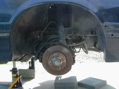
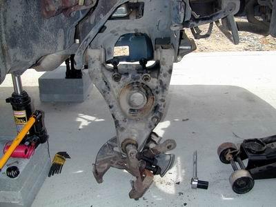
 Here
is an image of the empty wheel well... Finally, it's time to remove
the k-member. BUT, the k-member supports the engine, so you will
need to use a hoist, cradle, cherry picker, et al, to support the weight
of the engine. Here
is an image of the empty wheel well... Finally, it's time to remove
the k-member. BUT, the k-member supports the engine, so you will
need to use a hoist, cradle, cherry picker, et al, to support the weight
of the engine.
Take the load off the motor mounts just
enough to neutralize them. Spray penetrating oil on the horizontal
motor mount through-bolts and then remove them.
Use the lift, cradle, et al. to raise the
engine just enough to separate the engine w/ mounts from the mount adapter
attached to the k-member.
Now... finally... Remove the rear
k-member bolts. Take the dual captive nut assembly out, reinstall
the bolts into it, and place them in a safe place. You will be
re-using this hardware most likely.
|
 Rear
k-member to subframe bolts removed... Rear
k-member to subframe bolts removed... |
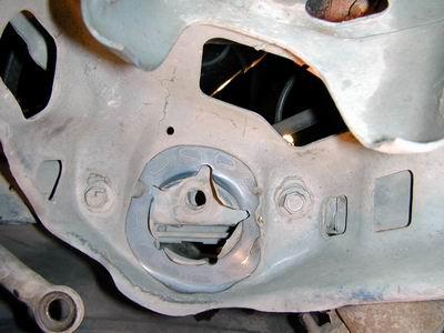 Here's
a shot of the upper k-member bolt heads looking up from under the
k-member. Note the upper coil spring seat in the center. Here's
a shot of the upper k-member bolt heads looking up from under the
k-member. Note the upper coil spring seat in the center. |
 Here's
an image of the tops of the upper k-member bolts. Note the captive
nuts. Here's
an image of the tops of the upper k-member bolts. Note the captive
nuts.
Break torque on all the bolts. Remove
the forward bolt from each side. Remove the rear bolt from one side
and re-install it finger tight. Remove the rear bolt from the other
side. Lower that side of the k-member and let it rest on the ground (or
prop it up to keep a bind off the remaining bolt/hole).
Remove the finger tight bolt from the other
side and lower the k-member to the ground.
|
 K-member
on the ground... K-member
on the ground...
Pull it from beneath the car, and remove
the motor mount adapters. You will need to re-use them, even if you
plan to replace the motor mounts.
|
 Motor
mount adapters removed. Reinstall the nuts on the adapters to
protect the threads. Motor
mount adapters removed. Reinstall the nuts on the adapters to
protect the threads.
Gather up all the removed parts and pieces
and keep them until you KNOW you won't need them again (essentially, until
you have completed the installation of the tubular suspension parts and
completed a successful test drive). |
| Well,
that's it for the removal. You can proceed to Part
2 now.
Let me know if you find this article
useful! EMAIL
Clay
|