| Construction
details of a routine (or otherwise less than interesting) nature has
been omitted. Prior to Fig. 1, a total of 6 each 23.5" x
23.5" x 0.75" MDF shelves were cut.
(NOTE: You may click on any image to pop up a larger version of the
image with arrows indicating action points.) |

Fig. 1 |

Fig. 2 |
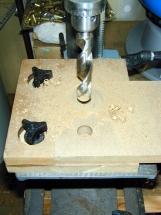
Fig. 3 |
| To
guarantee that the holes in all shelves would line up accurately, I
constructed a drill-press jig from scrap pieces of 0.75" MDF.
The jig is double thickness, such that the top layer provides
alignment and the lower layer prevents work piece tear-out and
protects the rather expensive 13/16" drill bit. Fig.1 shows the
procedure for setting the jig using a template with the proper
1.5" x 1.5" edge standoffs. |
Figure
2 is an overall view of the drill press with the jig properly set
and ready for testing. Note the presence of the cartridge cases and
tumbler in the background... it's a multi-use bench. (No
dangerous materials like powder or primer were anywhere near the
bench at the time.)  |
Using
some scrap pieces of 0.75" MDF from an earlier project, I
tested the jig setup. A good thing too, as the first template I
marked up was off a bit in one direction, which is a bad
thing... ANY error will be multiplied as you rotate the work
piece to drill each corner... Figure 3 shows the
"successful" test.... I drilled 3 identical rectangular
pieces of scrap and compared them to determine the variance (<
1/32"). So I drilled the shelves... |

Fig. 4 |
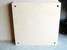
Fig. 5 |
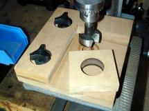
Fig. 6 |
| Here
is a corner shot of all six shelves. It was difficult to
steady them all with one hand and work the digital camera with the
other... Suffice to say that the accuracy was acceptable....
BTW, it takes some coordination to steady a 23.5" x 23.5"
piece of MDF in the jig without additional out supports on the drill
press, but it IS (obviously) possible. |
In
Fig. 5, you can see the shelves stacked and ready for finishing...
well almost. This is where I got another "idea". This bad
boy is gonna be HEAVY when finished... especially when the equipment
is stacked on it. Frankly, I didn't relish the idea of unloading the
rack to move it, much less what those all-thread rods will do for
the carpet I am planning to install soon. So.... |
I
decided to add "legs" to the bottom shelf. With the
all-thread, washer, and nut protruding from the bottom of the unit,
a standoff leg was required at each corner. I milled 4 each 3"
x 3" x 0.75" blocks for the standoffs. Then I bored a
relief hole in each using a 1.5" Forstner bit. Once
again, the jig came in very handy for repeatability. |
Fig. 7 |

Fig. 8 |

Fig. 9 |
| Figure
7 shows the "quick check" to see that the hardware would
have sufficient clearance once the blocks were glued in
place... (Not shown: blocks were glued and clamped in place at
the four corners of the bottom shelf.) |
I
had previously planned to "shoot" the shelves with Maglac
White Lacquer Undercoat and a Black Urethane Alkyd Gloss Enamel, but
the current conditions in my "shop" don't provide good
conditions for HVLP paint procedures (read: dust and traffic in and
out of the garage) So I decided to try my hand at applying Wilson
Art laminate (part # 1595 107 - horizontal grade, matte black). As
it turns out, the laminate will be less reflective (of course) and
probably more durable tahn the paint.... though not necessarily
easier/less time consuming to apply. Figure 8 shows one of the
shelves after scuff sanding it with 60 grit sandpaper to ready it
for cement application. (Not shown: scoring and snapping of
all laminate pieces: edges and flats. All edges have been applied
and routed flush at this point.) |
Here
is a shot just after applying the second coat of Wilson Art H20
Contact Cement. H20 is exactly what it sounds like... a waterborne,
low-VOC contact cement. It is quite a bit slower to
"flash" than traditional contact cements, but it is much
harder to come by here in CA these days. Note the white color of the
wet cement. It was in the high 90s in my garage at the time which
accounts for the color gradation in the picture. The cement becomes
"virtually clear" when it is ready for joining. On the
flats, I used 1 coat on the laminate and two coats on the MDF. The
first coat on the MDF is essentially a sealer coat which allows the
second coat to achieve the proper "build" for the bond.
The edge pieces required 3 coats on the MDF. Use dowels to hold the
laminate apart while aligning. Then set the laminate with a J-roller
beginning in the middle and working to the edges. Turn 90 degrees
and re-roll the piece from the middle out to assure the fullest
contact possible. |
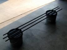
Fig. 10 |
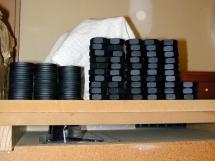
Fig. 11 |

Fig. 12 |
| The
lag time presented by the longer cement flash time allowed me to
work in other tasks. Figure 10 shows three of the 6' x
0.75" zinc-plated steel, all-thread rods getting a few coats of
flat black enamel spray paint. (Note: it is very difficult to get
full-coverage when spray painting all-thread... Also, it is VERY
highly recommended that you run all rods through a properly-sized
die to insure that the threads are clean and complete!!! |
Here
is the rest of the hardware after painting. Of note here are the
nuts. I found low-profile 3/4" nuts at McMaster Carr. They are
half the height of standard nuts and present a less-obtrusive
profile when installed on the flexi. (Note: buy and prep 5% over the
required amount of nuts, as you will likely have approximately 5%
with messed up threads... unless you want to run a tap through all
the nuts.) |
Remember
the "legs"? Well, here is the "rest of the
story". Blocks installed, and prior to laminating the flats, I
marked the mounting holes on the blocks and drilled 1/4" holes
approximately 3/4" deep to accept the "Slotted Drive,
Knife-edged, threaded, brass inserts" to accept the 6-32
machine screws. Using machine screws and inserts will allow for
multiple disassemblies without having to worry about screw pull-out
from the MDF. Also of note... I chose NOT to use standard casters.
Casters of sufficient weight-bearing capacity would have been huge,
ugly, and expensive. I chose these ball-bearing supported
"transfers"... again available at McMaster Carr. |

Fig. 13 |
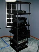
Fig. 14 |

Fig. 15 |
| Here
is a front view of the (nearly) completed Flexi-Rack. Sorry about
the lighting. The camera apparently metered off the silver-faced
Kenwood Model 600T FM Tuner, which made everything else much too
dark. Not yet installed (under the BFD DSP1124P) is the Crown
CE-1000a amp I just purchased for the soon-to-be-built Tempest
subwoofer. There is also room left in the rack for future addition
of a pre-pro, amp(s), and an ExactPower EP15A. |
Here
is an oblique view of the rack. It is currently sitting out in the
middle of the room while I finish installing components, make and
dress the cabling. Note the blue tape outline on the floor. that is
where the RPTV is SUPPOSED to be... it is getting a new green gun at
the moment. The front edge of the Flexi is flush with the RPTV when
in its "home". |
Finally,
a quick shot of the rear of the Flexi. I purposely chose a
23.5" depth to allow for components with large depth dimensions
(like the Denon AVR-4800), AND to give more room for dressing/hiding
cables, etc. It offers a great deal more stability as well. One more
note about the use of transfers instead of casters: The transfers
are a good compromise between casters and spikes. As they are
metal-to-metal and present a small "foot print", the
transfers are more like spikes than casters from a
stability/isolation standpoint. But more importantly, they make this
monster VERY easy to move, even on the carpet. Even my wife can move
the loaded rack... and you don't have to worry about which way the
casters are facing... it moves equally well in ANY direction. |
I
stated that it was "nearly" complete. Installing the
shelves caused quite a bit of "paint scrapeage" on the
rods, but that is easily fixed with a narrow point
"Sharpie" permanent marker (a Sharpie is great for black
touch-ups on virtually anything). But it is in service, the
"brown monster" entertainment system cabinet is history,
and I am well-pleased with how this project turned out. More
importantly, my wife likes it. And as we all know, THAT is the most
important thing when making major changes to anything outside the
garage and yard!  |

)
)
)
)
)
)
)
)
)
)
)
)
)
)
)