| Introduction:
One of the things that has always been a
nagging annoyance to me with respect to the Glock trigger is the
tendency for the stock trigger to deflect laterally when the pulling
force isn't applied directly rearward. Frankly, the Glock trigger
simply wiggles. Lateral movement in the trigger is bad for
repeatability/consistency in your trigger pull motion. This
applies whether you're running through an IPSC or IDPA stage, target
shooting, or (heaven forbid) using your weapon for self defense.
The main reason for this is that the
trigger pin to trigger pin through-hole clearance is too large. I
discovered this back when I owned a Glock 22, but the lateral play is
evident in all models. I've come up with a fix. I designed a
special trigger pin bushing that, when installed and tuned properly,
eliminates virtually 100% of the lateral play in the trigger.
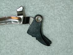
Here's an image of the bushing installed on my Glock 35 trigger bar.
Before installing the bushing, the
lateral play in my trigger was in excess of 0.004" (limited by the
trigger opening in the frame). Doesn't sound like a lot, but it
is. Compare a 0.004" lateral play in the Glock to a zero/near
zero deflection in a 1911/2011 (STI, SV, et al.).
Notice what I placed in parentheses
above, "limited by the trigger opening in the frame". IF
the frame opening were larger, the deflection would be even
greater. But worse, that "limiting" is actually adding
drag to the pull through via the trigger dragging on the frame
opening! Drag mean a larger pull weight, and it's NOT always
consistent. The more lateral load you apply to the trigger, the
greater the drag, resulting in a less than repeatable trigger pull
weight in actual use.
A lesser, but measurable, additional
problem with the large clearance is that the trigger and trigger bar can
actually displace vertically during the pull. Now, on a stock
trigger, this might not seem like such a big deal, but if you've tuned
your trigger bar to connector junction to get a lighter/smoother
trigger, the vertical displacement changes the point at which the two
parts contact.
The bushing is machined from an
oil-impregnated bronze material. As machined, the bushing has an
undersized inside diameter and is oversized in length. I had a
custom reamer made to match the inside diameter to the outside diameter
of a POLISHED trigger pin. The clearance is set to something on
the order of 0.001" max. Actually, it is something less than
this. Once the reaming is completed, the bushing is lapped to the
trigger pin with non-imbedding, ultra-fine lapping compound. The
abrasives in the compound are broken down by the lapping process.
The result is a very smooth and consistent match between the bushing and
trigger pin.
The bushing is pressed into the
trigger. The trigger is jigged into the drilling machine.
First, the existing through-hole is enlarged with a carbide drill bit to
facilitate entry of a reamer. Then a second custom reamer is run through
the trigger to set the through-hole diameter for an interference fit for
the bushing. The reamer size was chosen to 1) offer a permanent
interference fit, and 2) such that it would not over-stress the polymer
material in the trigger. Then, without removing the trigger from
the jig, the bushing is pressed into the trigger with another tool fixed
in the machine. The drilling machine is used as the arbor because
1) it doesn't take a great deal of force to press the bushing, and 2) it
minimizes the chance of misalignment between the bushing and the
trigger. Finally, the machine can be indexed to set the bushing's
lateral position within the trigger to locate the trigger in the frame
opening. |
|
With a nominal 0.001" clearance
distributed over the longer nominal length of the bushing, the maximum
deflection is less than 0.017 degrees. The stock deflection is on the
order of 0.742 degrees. That's a 97.79% reduction in lateral AND
vertical deflection of the trigger to trigger pin. It'd be great
if that was all there was to it, but it gets better.
With the bushing installed, we can locate
the trigger within the frame opening to eliminate/minimize any trigger
contact with (and hence drag on) the frame opening. This
significantly improves the pull consistency from cycle to cycle.
Additionally, (and I'm still analyzing
the "Why?") on my Glock 35, installation of the bushing
has significantly reduced deflection in the trigger bar arm in its path
around the magazine. In fact, setting the trigger centrally in the
frame opening, has actually eliminated the contact I used to have
between the trigger bar span and the frame adjacent to the mag
well. My supposition at this point is that reducing the lateral
deflection in the trigger also reduces the lateral deflection in the
trigger bar pin since they are both located in the same vertical
plane. I would assume that this is also making the trigger bar to
connector interface more consistent. I will have to do a wear
pattern test to verify this however.
Some other tips/tricks/lessons learned:
1) The slide stop lever's through-hole
for the trigger pin is a punched hole and thus is deformed. It's
important to lap the sides of the slide stop lever smooth to maximize
the bearing surface. Polish the mating surfaces after they are
flat.
2) The slide stop lever spring is more
than likely NOT properly aligned. (See my other
article). It's important to align the spring properly
before installation, and then make sure the spring tip is slid over
against the frame under the upper locking block pin (if any). One
alternative to make sure this is the case is to machine a shallow groove
in the locking block pin in the appropriate place to insure that the
slide stop lever spring stays properly located. However, doing
this will require you to depress the spring slightly when removing the
pin to prevent spring deformation.
3) Polish the inside surfaces of the
locking block legs where the trigger pin penetrate it on both sides.
4) Set the bushing length to a dimension
just slightly less than (the distance between the locking block legs
MINUS the width of the lapped flat slide stop lever). This will
minimize/reduce the rotational friction between the bushing, the right
locking block leg, and the inside face of the slide stop lever.
5) When you install the trigger pin, feel
for the click as the slide stop lever drops into the groove, and then
push the pin until the slide stop lever is pinned against the left side
of the frame. if you do this AND set a 0.001" clearance
between the left side of the bushing and the right face of the slide
stop lever, you will have minimum rotational friction AND maximize the
locational and deflection reduction effects of the bushing.
That's all for now... I will expand
on this article with more details, images, and How-To's as time permits!

Next...
|


